


The outline glyph view is the window in which most editing happens.
At the top of the window, underneath the menu bar is an information line. The first item is the location of the mouse pointer (in the internal coordinate system of the glyph). If there is a single selected point then the next item gives its location, and the next three are, respectively, the offsets from the selected point to the current location, the distance from the selected point, and the angle from the horizontal (measured counter-clockwise). Then we have the current scale factor, and the layer which is active. Finally (in the debugging view) is an indication of whether the instruction pointer is in the glyph program, the 'prep' program of the 'fpgm'.
Underneath the information is a ruler showing the current pointer location as a red line. There's a similar ruler on the left side.
Underneath that is the glyph itself. On the left edge of the screen is a grey line indicating the x=0 line, further right is a black line showing where the glyph's width is currently set. There are also grey lines showing the ascent, descent and baseline.
Background images and background splines are drawn in grey. Grid lines are also drawn in grey. Vertical hinting regions are drawn in light blue, Horizontal hints are drawn in light green. If any hints overlap the boundaries are drawn in cyan.
The points of the glyph are of three types, corner points drawn as filled squares, curve points drawn as filled circles and tangent points drawn as filled triangles. If a point is selected then it will be drawn as an outlined square, circle or triangle and its control points are drawn as little magenta or dull-cyan xs at the end of a similarly colored line. (in a curved point the control points will be collinear). (the "Next" control point will be drawn dull cyan, and the Prev point will be magenta).
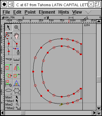 In a TrueType font, an on-curve point can be implied between
two control points. FontForge will draw these with an open circle.
The initial point in a contour will be drawn in green, and beside it will be a tiny arrow pointing in the direction of the contour.
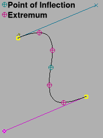 Sometimes it is important to know which points are at the extrema
of splines (postscript likes for there to be points at the extrema of all
splines), if this is important to you set the "Mark Extrema" flag in the
View menu. After that points at extrema will show up as dull purple. And
internal extrema will also be marked.
There are also two palettes, one, a layer palette, allowing you to control which layers are visible, and one, a tool palette, from which you may pick editing tools. Normally these are docked in the window, but you may choose to make them free floating windows by unchecking View->Show->Palettes->Dock Palettes.
You select an editing tool by clicking on the appropriate button on the tools palette, or you may depress the right mouse button and select a tool from a popup menu (you may also change layers and do a few other things with this menu). There are four different tools bindings available to you (this may be a complication with no utility). The left mouse button has a tool bound to it, and this tool will be displayed when the program is idle. If you hold down the control key, another tool is available, by default this is a pointer but if you click on the tools palette with the control key down you can select something else. If you depress the middle mouse button you get a third tool (by default a magnifying glass), and the control key and middle button give you the fourth (a ruler).
If the mouse pointer is close to a point (within a few pixels) when you depress the mouse, then the effective location of the press will be the location of the point.
If you drag a glyph from the font view and drop it into a glyph view then FontForge will drop a reference to the dragged glyph into the view.
Warning: If your glyph has truetype instructions then editing it may cause those instructions to behave very oddly. If your glyph has anchor points which depend on truetype point matching then editing the glyph may disconnect the points. If your glyph is used as a reference in another glyph that positions references by point matching then editing this glyph may reposition those references.
 There are several
drawing layers in the outline view. Each layer has an "eye box" (indicating
whether it is visible or not), curve type ("C" for cubic, "Q"for quadratic,
" " for Guide layer, which is always cubic), mode ("#" for Guide layer, "B"
for background layers, "F" for foreground layers) and a name.
The first layer is a set of guide lines/splines. These are common to all glyphs in the font. A few lines are provided for you (the x=0 line, the ascent, descent and baseline). Other handy lines might be the x-height of the font, the cap-height, ascender-height, descender-height, ... When you are working in any of the other layers, points will snap to splines in this layer (making it easy to force a consistent x-height for example).
Next are the background layers, these contain background images and splines. These do not go into the font, but may be helpful to you in tracing the outline of your glyph. It is possible to paste an image into the background if you have an image manipulation program that supports selection by mime type (the kde family of applications does this, perhaps others), then FontForge will be able to read images in either "image/png" or "image/bmp", otherwise you may import background image files.
When debugging truetype
(Hints->Debug), or showing
gritfit outlines (View->Show
Gridfit) the visibility of the gridfit outlines can be controlled
by the background layer's visibility.
The last is the foreground layer, this contains the splines that actually make up the glyph that will be placed into the font.
One can actually have multiple foreground and background layers. They can be created and deleted with "+" and "-" buttons. FontForge, won't delete last layer of its type, though. And care must be taken when generating a font to have the right foreground layer selected, if multiple are present.
Layer curve type and visibility can be toggled freely with left mouse button. Making the layer cubic or quadratic is a little trickier, as it's done with right mouse button: a pop-up menu will appear, allowing for some additional operations, like moving contents between layers.
 There are 19 different editing tools, a mode button which alters the behavior
of 5 of them, and two others (rectangle/ellipse and polygon/star) which come
in two forms.
At the bottom of the palette is a list of the current bindings of the mouse buttons. Here mouse button 1 is bound to the pointer tool, mouse button 1 with the control key pressed is also bound to pointer, mouse button 2 is bound to magnify, and mouse button 2 with control is bound to ruler.
Many of the tools have different behaviors if you hold the shift or alt (meta) key down when using the tool. On the mac there is no alt/meta key, and the Option and Command keys are usually bound to making a one button mouse look like a three button mouse. So on the mac fontforge uses the caps-lock key rather than alt/meta.
This tool is used for selecting points, images and referenced glyphs. It can also move these and scale images and referenced glyphs.
Only things that are in the layer that is currently editable may be selected or moved or scaled.
A simple click on an unselected point selects it and deselects everything else. A shift click on a point toggles whether that point is selected or not. A double click selects all points on the path containing that point. A tripple click selects everything in the layer. Clicking on the background will deselect everything. Clicking on the background and dragging out a rectangle will select everything within the rectangle. Clicking on a line or spline will select the two end points of that line or spline. Clicking on the dark part of an image (when in a layer with images) will select the image. Clicking on the outline of a referenced glyph will select that reference (if a reference glyph happens to have the same outline and bounding box, then holding down the meta/alt/caps-lock key will allow you to move it once it is selected, without the meta key you will resize it).
If a point has no visible control points, then they are at the same location as the point itself. If you want to select one of the control points then first select the point (to make the control points active) then hold down the meta key (use caps-lock on the mac) and depress the mouse on the point. This should allow you to drag one of the control points (if you get the wrong point the first time drag it out of the way, repeat the process to get the other control and then put the first one back). Sadly some window managers (gnome-sawtooth for one) will steal meta-clicks. If this happens you will need to use Element->Get Info to set the control points.
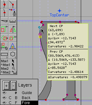 When you move
a control point you have the option
(
When you move
a control point you have the option
(View->Show Control Point
Info) of getting a popup box showing information about the control
point (and its opposite number on the other side of the on-curve point).
You will be told whether this is the next or previous control point, the
absolute location of the point, the offset from the on-curve point, the slope
expressed as a ratio, and as an angle, and the curvature on this side of
the base point. At the very bottom is the difference between the two curvatures.
Try to make this number approach 0 for curved points.
Once something is selected you may drag it around. If you select something and drag the mouse then it and everything else selected will be moved. If you drag an open path and one of the end points happens to fall on the end point of another open path, then the two will be merged into one (If you don't want open paths to merge, hold down the Alt/meta/caps-lock key). If you drag a control point then it will be moved (if you drag a control point defining an implied point, then the implied point(s) will also be moved).
If you selected a spline, then dragging it will drag the location on the spline where you pressed the mouse (so you are changing the shape of the spline).
If you hold the shift key down when you drag then the motion will be constrained to be either horizontal, vertical, or at a 45° angle. (When moving control points the combination of shift and meta (alt) will mean that the control point is constrained to be the same angle from the base point as it was before you started moving it).
If your font has an ItalicAngle set, and the ItalicConstrain preference item is set, then motion that would normally be constrained to the vertical is constrained to be along the ItalicAngle.
If you move the mouse to the bounding box of a selected image or reference glyph and drag it then you will scale that object.
If you move the mouse to the advance width line, then dragging it will change the width of the current glyph. If there are any bitmaps of this glyph then their widths will also be updated. If there are any other glyphs which depend on this glyph (ie. include this glyph as a reference) and their width was the same as the glyph's, then their widths will also be updated (so if you change the width of A, then the width of À, Á, Â, Ã, Ä and Å might also be changed). If you are displaying vertical metrics (in a font that has them), then you can use the same technique to modify the vertical advance.
If you are in an accented glyph then you may not be able to change the width, as its width is bound to that of the base glyph (By setting the "Use My Metrics" bit in the reference containing the base glyph). This will be displayed as a lock icon at the top of the window near the width line.
It is also possible to use the arrow keys to move selected items around. Each arrow will move the selection one em-unit (this can be changed in preferences to be any number of em-units) in the obvious direction. The selection may include the width (right bearing) line (or vertical with line). If the last thing you selected was a control point then that point will be moved. If you hold down the shift key at the same time the up and down arrows will move parallel to the italic angle (be careful of this: this leads to non-integral values). If you hold down the meta (alt) key, then the motion will be 10 times the normal amount.
If you hold down the control key while working with the arrows then the view will be scrolled rather than moving the selection.
If the glyph is a ligature (and has a ligature entry in Glyph Info) then it has the potential of having "ligature caret locations". Essentially this means that between each ligature component it is possible to place a caret location (so that the word processor will place be able to place a caret between each component of the ligature). In a ligature window a series of vertical lines will be drawn across the screen at the caret locations. By default these lines will be placed at the origin, but you may move one by placing the mouse pointer on it, depressing the button and dragging the line around. See the description on building a ligature for a more complete description.
Clicking with the magnifying tool will magnify the view and center it around the point you clicked on. Holding down the Alt/Meta/CapsLock key and clicking will minify the view, again centered around the point at which you clicked. Again some window managers will steal meta-clicks, so you may have to use the View menu to minify (It's called Zoom Out
If you drag out a rectangle with this tool then when you release, FontForge will shift and scale the view so that your rectangle just fits into the window.
If your mouse has a scroll wheel then holding down the control key with the scroll wheel causes it to magnify or minify the window.
You can use this tool to scroll the window without using the scroll bars.
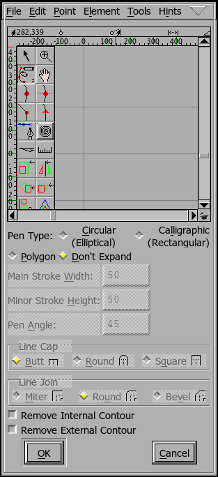 The
freehand tool
You can use this tool to draw a random curve which FontForge will then attempt to convert into a set of splines. If you hold down the Alt/Meta/CapsLock key then FontForge will close the curve when you release the mouse.
If you double click on the icon in the tool palette you get a dialog similar
to the Element->Expand Stroke which
will give you slightly more control over the results, as you can have it
not expand the stroke you draw (ie. leave a single trace.)
These four tools behave similarly, differing only in what kind of point is added to the view.
If a single point is selected, and if that point is at the end of a path then depressing the mouse button will create a new point where the mouse was depressed and draw a spline from the selected point to new point. If this new location happens to be the end of a path then the two paths will be joined (or if it is the end of the current path then the path will be closed).
Otherwise if the mouse is depressed while being on a spline then a point will be added to that spline.
Otherwise a new point is created not on any path at the location of the press.
Once the point has been created then it becomes selected and all others are deselected. You may drag the point around, and if the point is on an open path and you drag it to the end point of another open path then the two paths will be joined.
If you double click then a point will be added as above and a Point Info dlg will appear to give you fine control over the location of the point and its control points.
The four different point types are
This tool behaves differently in cubic and quadratic editing. In many ways it is similar to the tools above as it adds a point to the current spline.
In a cubic font the points created are curved points, and they are initially created with the control points on the point and as you drag you drag out the control points rather than moving the point itself around.
In a quadratic font a point will be created half-way between the last control point and the current location (which becomes the next control point).
If you hold down the Alt (Meta, etc) key you change the behavior so that cubic editing looks like quadratic and vice versa.
These tools add spiro control points to the current contour, these are only available in spiro mode, but the basic adding process is similar to the above.
The different point types are:
This is based on Raph Levien's work with clothoid splines which provide constant curvature across points.
This button toggles between editing contours using Bézier control points, or between using spiro (clothoid) control points.
This tool is used to cut splines. As you drag it across the view fontforge draws a line showing where the cut will happen. When you release, every spline you intersect will be cut-- that is at the location where this line intersects the spline two new points will be created and the old spline will be split in two connecting to the two new end points. These endpoints are not joined, so the spline is now open (or if it were previously open, it is now cut in two).
 This tool tells
you the current position of the mouse. If the mouse is near the outline it will
give the slope and curvature there. If the mouse is near a point on the outline
will give the slope and curvature on each side of the point.
If you depress the button and drag, the first line of the tool's pop-up shows the distance, angle and (x-y) offsets from the first point where you depressed the mouse to the last point, the mouse's current location. The next lines in the pop-up show information about points along the line that intersect splines, including the start and end points of the line itself. If there are more than two intersections then the x, y, and total distance between the first and last intersections are shown before the point list.
[0] indicates the starting point of the measure line, and the (x-y) co-ordinates of that point. Initially [1] is the end point; when it intersects with one spline then [1] becomes the first intersection point and [2] becomes the end point, and so on. The co-ordinates are followed by the x and y distances and then the final number is the length of the section ending at that point; which is also shown directly on the canvas.
If you hold down the Meta/Alt/CapsLock key then information will only be shown when the mouse is depressed.
This tool allows you to scale the selection by eye rather than by a set amount (if there is no selection then everything in the current layer will be scaled). The location of the press will be the origin of the transformation, the further you move the point up and to the right the more it will be scaled in that dimension. If you want the scaling to be uniform or only in one dimension then hold down the shift key.
Double clicking on this will bring up the transform dialog with the "Scale..." option selected.
This tool allows you to flip the selection either horizontally or vertically. Again the point at which you press the mouse is the origin of the transformation.
Double clicking on this will bring up the transform dialog with the "Flip..." option selected.
Note: After flipping an outline you will almost certainly want to apply Element->Correct Direction.
This tools allows you to rotate the selection freely.
Double clicking on this will bring up the transform dialog with the "Rotate..." option selected.
This tool allows you to skew the selection.
Double clicking on this will bring up the transform dialog with the "Skew..." option selected.
This tool allows you to rotate the selection in the third dimension and project the result back onto the x-y plane. An imaginary line is drawn from the point where you pressed to the current point, this line determines the axis of rotation. The distance you move from the initial press determines the amount of rotation.
Double clicking on this will bring up the transform dialog with the "Rotate 3D..." option selected.
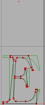
This tool allows you to apply a perspective transformation to the selection (this is a non-linear transformation). This tool uses three points: The glyph origin, the press point, and the current location of the cursor. In the image at right the mouse was pressed on the baseline near the glyph's advance width, and the mouse was released in the upper middle of the image. The glyph is transformed so that the release point is treated as the point at infinity. The line between the origin and the press point defines one axis of the transformation. Distances perpendicular to this line are retained, distances parallel to it are scaled as:
x' = release_x + (release_y - y)/release_y * ( x - release_x )
y' = y
By default this produces a rectangle, single-clicking on the tool palette will toggle between rectangle and ellipse, and double clicking in the tools palette gives you a dialog which allows you to control whether your rectangles are drawn with round corners, and how both rectangles and ellipses are specified.
You can choose whether the rectangle (or ellipse) will be drawn between the point where you depressed the mouse on the view and the point where you released it (bounding box), or whether the point where you depress the mouse becomes the center of the rectangle and the point where you release it provides an end-point (center out).
If you want even more control, you can double click in the glyph view and get another dialog which allows you to define numerically where the rectangle/ellipse should be placed, how big it should be, and whether it should be rotated.
By default this draws a regular polygon, but by double clicking on the button in the tools palette you can make it draw a star, or select the number of verteces in your polygon.
The polygon is drawn as though it were inscribed in the circle whose center is the point where you depressed the mouse and whose radius is the distance between the press point and the release point. One of the polygon's verteces will be at the release point.
A star is drawn similarly. It will be a star generated from a regular polygon. As the number of verteces of the polygon gets larger the star will look more and more like a circle, for this reason the dialog box that allows you to pick the number of verteces will also allow you to pick how far the star's points should extend beyond the circle in which the polygon is inscribed (this will make a non-regular star, but it might look nicer).
 In this
view the vertical metrics of the glyph are shown. You can change the vertical
advance just as you changed the glyph's width (by selecting the pointer tool
and dragging the vertical advance line up or down).
 If you have
the freetype library, then you can see the results of rasterizing your glyph.
If you have freetype's bytecode interpreter enabled you can also see how
the truetype instructions in the glyph have moved the points around (if you
don't have the bytecode interpreter enabled you will see what freetype's
autohinter does to points). This mode can be invoked with
If you have
the freetype library, then you can see the results of rasterizing your glyph.
If you have freetype's bytecode interpreter enabled you can also see how
the truetype instructions in the glyph have moved the points around (if you
don't have the bytecode interpreter enabled you will see what freetype's
autohinter does to points). This mode can be invoked with
View->Show Grid
  Fit
...
The Show Grid Fit command will ask you for some basic information first.
It needs to know the pointsize and resolution for which you want the action
performed (the example at right is 12pt on a 72dpi screen).

 The
Debugging View
"I told you butter wouldn't suit the works!" he added, looking angrily at the March Hare."It was the best butter," the March Hare meekly replied.
Alice's Adventures in Wonderland
Lewis Carroll
FontForge has a truetype debugger -- provided you have a version of freetype on your machine with the bytecode interpreter enabled (Note: you need a license from Apple to enable this. It is protected by several patents).
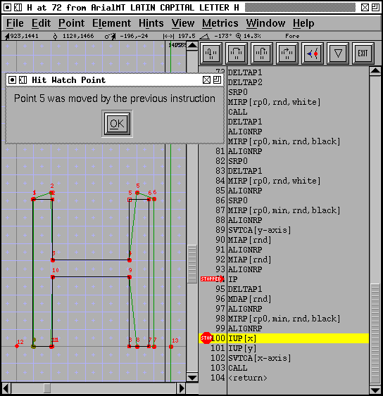
The image to the right shows an example of this mode. You invoke it with
Hints->Debug, and as with
the grid-fit view above you must establish a pointsize and and resolution.
The view divides into two panes, the left of which is similar to the grid
fit view above (except that it changes as you step through the instructions),
the right pane provides a list of the instructions to be executed.
In addition to showing you all the points in your glyph there are either 2 or 4 additional points. These are the so-called "phantom" points and represent the horizontal and vertical metrics of the glyph (old versions of freetype will only display 2 points -- left side bearing and advance width, while newer versions will display top side bearing and advance height as well).
As you step through a glyph occasionally points will light up. This is FontForge's attempt to show you what points will be affected (usually moved) by the current instruction. Other points will have a circle drawn around them. These are used as reference points by the instruction.
There are a series of buttons at the top of the instruction view. The first will single step the truetype program (step into), the second will step over procedure calls, the third will set a break point at the return point for the current function and continue until that is hit, and the fourth will continue until:
The red "STOPPED" arrow shows the current location of the instruction pointer (and what instruction will be executed next).
The fifth button allows you to set a watch point. You select a point (or several points) in the left hand pane, and press this button. Thereafter, whenever one of those points is moved FontForge will stop the glyph program. (You may also set watch points through the points window).
When you are in this mode there are a few special "hot keys"
r run/restart k kill/quit debugger q kill/quit debugger c continue s step (into) n next (step over) f finish function (continue until we return from the function)
Similarly you may watch storage and cvt locations by clicking on the appropriate spot in the storage and cvt windows.
You can set a more conventional break point by clicking on an instruction. A little red stop sign will appear on top of the address area, and the program will halt when the instruction pointer reaches that instruction. Clicking on the instruction again will remove the breakpoint.
Flaw: Currently there is no way to set breakpoints outside of the current function (or glyph).
Flaw: Currently there is no way to examine the call stack.
The sixth button brings up a menu with which you can control which of various debugging palettes are visible. The ones available so far are: Registers, Stack, Points, Storage, Cvt, Raster and Gloss.
 |
 |
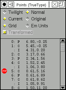 |
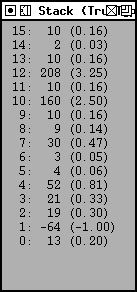
| Shows the truetype graphics state. | Shows the truetype stack. The value in parentheses is a 26.6 number. | Shows the points. You may choose to view the twilight points, or the
points displayed in the glyph pane (the normal points). You may view the
current location or the original location. You may view them in the units
of the current grid, or in em-units.
When debugging a composite glyph the Transformed check box indicates whether the points of the current component have been transformed (to show where they fit in the composite) or not (showing where they are in the base component -- this is what the instructions are working on). The points may have some flags associated with them: 'P' means the point is an on curve point, 'C' means the point is an off curve point (a control point), 'I' means the point is an on-curve point interpolated between two control points, 'F' means a phantom point, 'T' means a twilight point, 'X' means the horizontal touch flag has been set, 'Y' means the vertical touch flag has been set. A small stop sign indicates the point is being watched (that is execution will stop if the point moves). You may change whether a point is watched by clicking on it. Contours are separated by horizontal lines |
 |
 |
 |
| Shows the truetype storage locations.
A small stop sign indicates the storage location is being watched (that is execution will stop if the location changes). You may change whether a location is watched by clicking on it. |
Shows the current values in the cvt array.
A small stop sign indicates the cvt location is being watched (that is execution will stop if the value changes). You may change whether a location is watched by clicking on it. |
Shows the current raster with no magnificaton |
|
| This window tries to provide a gloss for the current instruction. It gives a brief description of the instruction in the top few lines, then explains what registers it uses, and shows their values, it shows what use is made of the stack and attempts to interpret the data on the stack. Finally it explains what registers will be set, and what will be pushed onto the stack. |
The final button will exit the debugger.
The debugger also responds to some single character commands common to many debuggers:
| s | step into |
| n | step over (next) |
| c | continue |
| r | restart (with same grid) |
| f | step out (finish routine) |
| k | kill the debugger |
| q | kill the debugger |
The Hints->Debug menu command can also be used to exit the debugger (by turning off the debug check box), or to restart the debugger with different values for the point size and resolution. This dlg can also control whether the fpgm and prep tables are debugged. Usually debugging will start when execution reaches the instructions associated with this glyph.
FontForge is not as friendly when debugging composite glyphs as it should be -- this is influenced by the way truetype works. Suppose you want to debug the "Atilde" glyph.
First FontForge will load and grid fit the "A" glyph, points from the "tilde" will not be displayed and behavior will be exactly the same as if you were debugging a stand alone "A".
Then FontForge will load and grid fit the "tilde" glyph, and now points from the "A" glyph will not be visible. The point numbers on the "tilde" will be the same as they are in a stand-alone "tilde" (whereas in a true representation of "Atilde", the points numbering in the "tilde" component will be offset by the number of points in the "A" component). The "tilde" may appear oddly positioned, this is caused by rounding: the "tilde" will usually be translated, and this translation will usually be rounded to fit the pixel grid. The width line will show the width of the "tilde" and not of the "Atilde".
Finally FontForge will execute any instructions in the composite itself, now all sub-components will be displayed, and all points will be numbered as they should be.
Several words of caution:
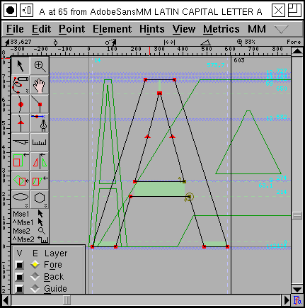 Intermediate version of "A" with two other styles in the background |
In a multiple master font the MM menu
gives you control over which style of the font you are editing. It will also
allow you to display any (or all) of the other styles in the background.
Although the menu is called "MM" it applies equally to Apple's distortable
fonts ("*var" fonts, like Skia).
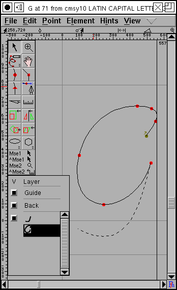 If
you wish to edit type3 fonts,
FontForge can display a glyph broken
down into a series of strokes and fills and allow you to edit each one.